


SM Power Fuses
For outdoor distribution, 4.16 kV through 34.5 kV
For use with SM Refill Units, S&C SM Power Fuses are especially suited for protecting transformers, capacitor banks, and cables in outdoor distribution substations
SM Power Fuses are especially suited for protecting transformers, capacitor banks, and cables in outdoor distribution substations through 34.5 kV. Their precision-engineered nondamageable silver or nickel-chrome fusible elements have time-current characteristics that are precise and permanently accurate — assuring not only dependable performance, but also continued reliability of system coordination plans.
With SM Power Fuses, source-side devices may be set for faster operation than practical with other power fuses or circuit breakers, thereby providing better system protection without compromising coordination.
SM-4 Power Fuses, rated 200 amperes continuous, utilize SM-4® Refill Units. These refill units are offered in a variety of ampere ratings, in three different speeds — S&C Standard, Slow, and Coordinating. They provide interrupting ratings of up to 15,600 amperes symmetrical.
SM-5 Power Fuses, rated 300, 400, or 720 amperes continuous, utilize SM-5® Refill Units. These refill units are similarly offered in a variety of ampere ratings, in three different speeds — S&C Standard, Slow, and Coordinating. They provide interrupting ratings of up to 34,000 amperes symmetrical.
This broad selection of ampere ratings and speeds permits close fusing to achieve maximum protection and optimum coordination. SM-4 and SM-5 Power Fuses are manufactured in accordance with a quality system certified to ISO9001:2000.
(On mobile, swipe left for remaining ratings information.)
| Fuse Type | kV | Amperes, RMS, Symmetrical | ||||
|---|---|---|---|---|---|---|
| Nominal | Maximum | BIL | Maximum | Interrupting | ||
| 60 Hz | 50 Hz | |||||
| SM-4 | 7.2 14.4 25 34.5 |
8.3 17.0 27 38 |
95 110 150 150 & 200 |
200E 200E 200E 200E |
15 600 12 500 9 400 6 250 |
15 600 12 500 9 400 6 250 |
| SM-5 | 7.2 14.4 14.4 25 34.5 |
8.3 17.0 17.0 27 38 |
95 110 110 150 150 &200 |
400E & 720E 400E 720E 300E 300E |
26 000 34 000♠ 25 000 20 000 17 500 |
26 000 25 000 25 000 20 000 17 500 |
♠ 25 000 amperes for systems above 15.5 kV thru 17.0 kV.
Fast, positive fault interruption is achieved in SM-4 and SM-5 Refill Units through high-speed elongation of the arc in the solid-material-lined bore, and by the efficient deionizing action of gases generated through thermal reaction of the solid material due to the heat of the confined arc.
Here’s How it Works
- Overcurrent melts the fusible element. The strain wire severs, initiating arcing.
- Both the main and auxiliary arcing rods are drawn upward by the spring-and-cable assembly in the holder. After approximately 1/8-inch travel, the lower section of the auxiliary arcing rod engages the auxiliary contact, momentarily shorting out the arc.
- For low-magnitude faults, arcing is reinitiated in the small-diameter auxiliary bore when the tip of the auxiliary arcing rod travels about one inch (and clears the auxiliary contact).
- For moderate-to-high-faults, the auxiliary arcing rod — which momentarily provides the only path for the fault current — quickly melts at its reduced section, and separates from the one-inch long arcing tip. Any arcing in the auxiliary bore can’t persist, and quickly transfers to the main arcing rod in the main bore.
- For low-magnitude faults, the large-diameter section of the auxiliary bore delays arc extinction until a sufficient gap is attained, precluding reignition in the main bore.
- For moderate-to-high faults, the arc is lengthened as the main rod is drawn upward into the main bore. The large circumference of the main bore provides greater surface exposure of the arc-extinguishing medium to the heating effects of the arc, thereby enhancing generation of arc-quenching deionizing gases.
- For low-magnitude faults, after the auxiliary arcing rod has traveled about one-half stroke, sufficient deionization has occurred to extinguish the arc.
- For moderate-to-high faults, after the main arcing rod has traveled about one-half stroke, sufficient deionization had occurred to extinguish the arc.
SM Fuse Units — Fusible Element
SM-4 and SM-5 Refill Units feature silver or pretensioned nickel-chrome current-responsive elements that are drawn through precision dies to very accurate diameters. They’re of solderless construction, brazed into their terminals. Melting time-current characteristics are precise, with only 10% total tolerance in melting current, compared to the 20% tolerance of many fuses.
These design and construction features assure that SM-4 and SM-5 Refill Units conform to their time-current characteristics on a sustained basis. They’re corrosion-resistant and nondamageable. Age, vibration, and surges that heat the element nearly to the severing point won’t affect their characteristics.
The nondamageability of of SM-4 and SM-5 Refill Units provides these important advantages:
- Superior transformer protection. You can fuse close to the transformer full-load current and thus protect against a broad range of secondary-side faults.
- Higher levels of service continuity. “Sneakouts” (unnecessary fuse operations) are eliminated.
- Close coordination with other protective devices. No “safety zones” or “set-back allowances” are needed to the published TCCs to protect the element against damage.
- Operating economies. No need to replace unblown companion fuses on suspicion of damage following a fuse operation.
1, 2, and 3E

5E and 7E
![]()
10E and larger
![]()
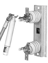
Disconnect 180° Opening, Vertical Style, 14.4-kV SM-4 Power Fuse
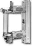
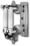
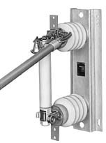
Disconnect 180° Opening, Parallel-Mounted Style, 14.4-kV SM-5 Power Fuse
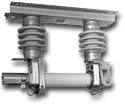
Disconnect 90° Opening, Inverted Style, 14.4-kV SM-5 Power Fuse
Opening and Closing SM Power Fuses
SM Power Fuses may be easily opened or closed using a universal pole equipped with an S&C Station Prong.
SM Power Fuses must not be opened under load, with one exception: Type SM-4 Power Fuses in the Disconnect 180° Opening Vertical Style may be furnished with an optional attachment hook, for full-load live switching with Loadbuster®, S&C’s portable loadbreak tool.
Installing or Removing Holders
SM Power Fuse Holders can be installed in or removed from the mounting using a Universal Pole equipped with an S&C Station Prong.
Lifting holder out of (or into) a Non-Disconnect Style SM Mounting
Closing (or opening) the clamping arm on the fuse clip
| Curve Type | kV Nom. Ratings | Fuse Type | TCC Number | Excel | |
|---|---|---|---|---|---|
| Minimum Melting | All | SM-4 and SM-5 | TCC Number 153-4 | EXCEL | |
| Total Clearing | 4.6 through 14.4 | SM-4 and SM-5 | TCC Number 153-4-2 | EXCEL | |
| Total Clearing | 25 and 34.5 | SM-4 and SM-5 | TCC Number 153-4-4 | EXCEL |
| Curve Type | kV Nom. Ratings | Fuse Type | TCC Number | Excel | |
|---|---|---|---|---|---|
| Minimum Melting | All | SM-4 and SM-5 | TCC Number 115-4 | EXCEL | |
| Total Clearing | 4.6 through 34.5 | SM-4 and SM-5 | TCC Number 115-4-4 | EXCEL |
| Curve Type | kV Nom. Ratings | Fuse Type | TCC Number | Excel | |
|---|---|---|---|---|---|
| Minimum Melting | All | SM-4 and SM-5 | TCC Number 119-4 | EXCEL | |
| Total Clearing | 4.6 through 14.4 | SM-4 and SM-5 | TCC Number 119-4-2 | EXCEL | |
| Total Clearing | 25 and 34.5 | SM-4 and SM-5 | TCC Number 119-4-4 | EXCEL |
| Curve Type | kV Nom. Ratings | Fuse Type | TCC Number | Excel | |
|---|---|---|---|---|---|
| Minimum Melting | All | SM-4 | TCC Number 179-4 | EXCEL | |
| Total Clearing | 14.4 | SM-4 | TCC Number 179-4-2 | EXCEL |
| Curve Type | kV Nom. Ratings | Fuse Type | TCC Number | Excel | |
|---|---|---|---|---|---|
| Minimum Melting | All | SM-5 | TCC Number 173-4 | EXCEL | |
| Total Clearing | 7.2 and 14.4 | SM-5 | TCC Number 173-4-2 | EXCEL |
| Curve Type | kV Nom. Ratings | Fuse Type | TCC Number | Excel | |
|---|---|---|---|---|---|
| Minimum Melting | All | SM-5 | TCC Number 174-4 | EXCEL | |
| Total Clearing | 14.4 | SM-5 | TCC Number 174-4-2 | EXCEL |


