


Mark VI Circuit-Switcher
For outdoor transmission, 69 kV through 138 kV
Mark VI Circuit-Switchers with pre-insertion inductors are the most reliable way to switch and protect substation capacitor banks
The Mark VI Circuit-Switcher offers the latest in interrupter technology. It features a 31.5-kA fault-interrupting rating and 3-cycle interrupting time with simultaneity of less than ¼ cycle. No shunt-trip device is needed. The Mark VI Circuit-Switcher is significantly lighter than the Mark V Circuit-Switcher, is easier to install, and has reduced maintenance requirements.
The Mark VI Circuit-Switcher uses the same rugged integral disconnect as the Mark V, making it perfect for use with pre-insertion inductors.
- Higher-than-ever 31.5-kA fault-interrupting rating and 3-cycle interrupting time.
- Three-phase tripping by electrically linked interrupters — provides tripping simultaneity of less than ¼ cycle.
- Hermetically sealed interrupters — eliminates the hassle of field-filling with SF6 gas. Interrupters provide full dielectric ratings when open.
- Reliable performance — Mark VI uses the same robust high-speed disconnect as Mark V Circuit-Switcher and the heavy-duty Mark VI CS-1A Switch Operator.
Optional features include:
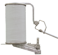
- Pre-insertion Inductors. With the addition of pre-insertion inductors, Mark VI Circuit-Switcher is ideal for capacitor-bank applications, combining switching, protection, and transient overvoltage control in one device. Pre-insertion inductors limit inrush current and overvoltage at the capacitor-bank bus, limit phase-to-phase switching-surge overvoltages at remote transformers, and control overvoltages on long, open-ended lines and on the user’s utilization-voltage bus.
- S&C Mounting Pedestals. Dramatically reduce installation time with S&C’s easy-to-install mounting pedestals.
Voltage and Continuous, 4-Hour, Peak Withstand, and Fault-Closing Current Ratings — 50/60-Hz.
| kV | Amperes, RMS | ||||||
|---|---|---|---|---|---|---|---|
| Nom. | Max | BIL | Cont. | 4-Hour | Peak Withstand | 1-Second | Fault-Closing, Duty-Cycle, Two-Time |
| 69 | 72.5 | 350 | 420 | 630 | 81 900 | 31 500 | 30 000 |
| 115 | 123 | 550 | 420 | 630 | 81 900 | 31 500 | 30 000 |
| 138 | 145 | 650 | 420 | 630 | 81 900 | 31 500 | 30 000 |
Interrupter Current Ratings For Shunt Capacitor Bank Switching and Protection
| Class | Qualifications | Maximum Amperes, Interrupting RMS Symmetrical | |||||
|---|---|---|---|---|---|---|---|
| Bank Current Switching | Grounded capacitor banks applied on solidly grounded systems only, through 138 kV | 420 | |||||
| Ungrounded capacitor banks through 138 kV | 420 | ||||||
| Fault Interrupting | — | 31 500 | |||||
Interrupter Current Ratings For Transformer Switching and Protection
| Class | Qualifications | Maximum Amperes, Interrupting RMS Symmetrical |
|---|---|---|
| Load Dropping | — | 630 |
| Duty-Cycle Fault Interrupting | 3-Time | 31 500 |
| 5-Time | 18 900 | |
| 10-Time | 9 450 | |
| 30-Time | 3 150 | |
| Secondary Faults | 69 kV | 4 200 |
| 115 kV through 138 kV | 2 600 | |
|
Internal faults — see both primary and secondary faults, above
|
||
Pre-insertion inductors are especially suited for limiting transient overvoltages which, through voltage manification, can result in nuisance tripping of adjustable-speed drives and other sensitive electronic devices. Voltage magnification can occur where power-factor correction capacitors and/or voltage control capacitors are applied on the utility distribution system or on a utility customer’s low voltage bus, and is caused by a near-resonant condition between the switched capacitor bus and the capacitances at lower voltages.
Pre-insertion inductors are more effective than controlled-closing schemes and pre-insertion resistors for limitation of:
- Inrush current and overvoltage at the capacitor bank bus — curbing induced transients in substation low-voltage circuits that can cause spurious signals, insulation puncture, and component damage.
- Switching-surge overvoltages at remote transformers — which can lead to decreased transformer life, or even failure.
- Overvoltages on long open-ended lines. Such overvoltages can cause nuisance arrestor operation.
- Transient overvoltages on users’ utilization-voltage bus — voltage magnification of capacitor-switching transients can cause nuisance tripping of adjustable-speed drives and other sensitive electronic devices.
How does the pre-insertion inductor work?
First, an open-air arc makes up the initial circuit through the pre-insertion inductor. The inductor core picks up the inrush current before it reaches the main contact. Then, the pre-insertion inductor is bypassed, and disconnected as the moving arcing rod rotates. As the main contact is made, the pre-insertion inductor is completely removed from the circuit.

The sliding contact arrangement places the pre-insertion inductor in the circuit for only a few cycles. That’s how long it takes to provide high-quality transient control.
For complete application information on S&C Pre-insertion Inductors refer to S&C Data Bulletin 711-95 or contact the nearest S&C Sales Office.
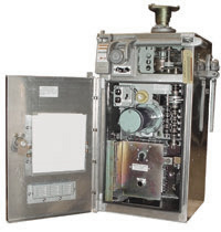
The Mark VI CS-1A Switch Operator direct-drives the vertical-break disconnect of the Mark VI Circuit-Switcher. It provides trip-free capability. Should the Mark VI be inadvertently closed into a fault sensed by user-furnished relays, Mark VI will trip immediately.
The operator features a sturdy welded enclosure with baffled louvers that allow air circulation, but keep out rain. The interior of the weatherproof, dustproof enclosure is accessed by a hinged door . . . rather than removal of the entire enclosure.
The Mark VI CS-1A Switch Operator includes:
- Six adjustable auxiliary switch contacts, coupled to the motor
- External trip and close push buttons with padlockable cover
- Built-in manual operating handle for the disconnect
- Decoupling mechanism that allows decoupling and locking of the disconnect in the open position
- Mechanical position indicator
- Non-resettable operation counter.
Optional features for the Mark VI CS-1A Switch Operator include:
- Additional auxiliary-switch contacts
- LED position indicating lamps
- Remote-control blocking switch
- Space-heater thermostat
- Duplex receptacle with ground-fault circuit interrupter, and convenience light lampholder with switch.


