


SMD® Power Fuses - Outdoor Distribution
For use at 14.4 kV through 34.5 kV
Offering full-fault-spectrum protection, SMD Power Fuses detect and interrupt all faults—large, medium, and small—even down to minimum melting current
SMD Power Fuses are especially suited for protecting transformers, capacitor banks, and cables in outdoor distribution substations through 34.5 kV. They incorporate precision-engineered nondamageable silver or nickel-chrome fusible elements with time-current characteristics that are precise and permanently accurate — assuring not only dependable performance, but also continued reliability of system coordination plans.
With SMD Power Fuses, source-side devices may be set for faster operation than practical with other power fuses or circuit breakers, thereby providing better system protection without compromising coordination.
SMD-20 Power Fuses, rated 200 amperes continuous, utilize SMU-20 Fuse Units. These fuse units are offered in a variety of ampere ratings, in five different speeds — S&C “K,” Standard, Slow, Very Slow, and “DR.” They provide interrupting ratings of up to 14,000 amperes symmetrical at 60 Hz.
SMD-40 Power Fuses, rated 400 amperes continuous, utilize SMU-40 Fuse Units. These fuse units are similarly offered in a variety of ampere ratings, in four different speeds — S&C “K”, Standard, Slow, and Very Slow. They provide interrupting ratings of up to 25,000 amperes symmetrical at 60 Hz.
This broad selection of ampere ratings and speeds permits close fusing to achieve maximum protection and optimum coordination. SMD-20 and SMD-40 Power Fuses are manufactured in accordance with a quality system certified to ISO9001:2000.
(On mobile, swipe left for remaining ratings information.)
| Fuse Type | kV | Amperes, RMS, Symmetrical | ||||
|---|---|---|---|---|---|---|
| Nominal | Maximum | BIL | Maximum | Interrupting | ||
| 60 Hz | 50 Hz | |||||
| SMD-20 | 14.4 14.4 14.4 25 34.5 |
17.0 17.0 17.0 27 38 |
110 125 150 150 200 |
200E or 200K 200E or 200K 200E or 200K 200E or 200K 200E or 200K |
14 000 14 000 14 000 12 500 10 000 |
11 200 11 200 11 200 10 000 8 000 |
| SMD-40 | 4.8 14.4 25 |
5.5 17.0 29 |
95 110 150 |
400E 400E 400E |
25 000 25 000 20 000 |
20 000 20 000 16 000 |
Fast, positive fault interruption is achieved in SMU-20 and SMU-40 Fuse Units through high-speed elongation of the arc in the solid-material-lined bore, and by the efficient deionizing action of gases generated through thermal reaction of the solid material due to the heat of the confined arc. The resultant high rate of dielectric recovery voltage more than matches the transient recovery voltage severity of the circuit.
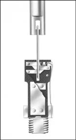
Here’s How it Works
- Overcurrent melts the fusible element, shown below. The strain wire severs, initiating arcing.
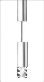
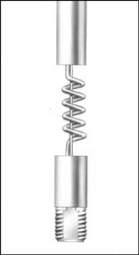
- Released force of the drive spring accelerates the arcing rod upward, causing rapid elongation of the arc in the solid-material-lined bore.Under maximum fault conditions, heat from the confined arc causes solid material in the large-diameter lower section of the arc-extinguishing chamber to undergo thermal reaction, generating turbulent gases and effectively enlarging the bore diameter so that the arc energy is released with a mild exhaust. Under low-to-moderate fault conditions, the arc is extinguished in the small-diameter upper section of the arc-extinguishing chamber, where deionizing gases are effectively concentrated for efficient arc extinction.
- Continued upward travel of the arcing rod after arc extinction causes the actuating pin to penetrate the upper seal, initiating positive dropout of the fuse unit.
SMU Fuse Units — Fusible Element
SMU Fuse Units feature silver or pretensioned nickel-chrome current-responsive elements that are drawn through precision dies to very accurate diameters. They’re of solderless construction, brazed into their terminals. Melting time-current characteristics are precise, with only 10% total tolerance in melting current, compared to the 20% tolerance of many fuses.
These design and construction features assure that SMU Fuse Units conform to their time-current characteristics on a sustained basis. SMU Fuse Units are corrosion-resistant and nondamageable. Age, vibration, and surges that heat the element nearly to the severing point won’t affect their characteristics.
The nondamageability of SMU Fuse Units provides these important advantages:
- Superior transformer protection. You can fuse close to the transformer full-load current and thus protect against a broad range of secondary-side faults.
- Higher levels of service continuity. “Sneakouts” (unnecessary fuse operations) are eliminated.
- Close coordination with other protective devices. No “safety zones” or “set-back allowances” are needed to the published TCCs to protect the element against damage.
- Operating economies. No need to replace unblown companion fuses on suspicion of damage following a fuse operation.
1 ampere
3K, 5E, and 7E
6K through 200K, 10E through 200E, and 10DR through 20DR
Overhead-Pole-Top Style 14.4-kV SMD-20 Power Fuse (25 kV is similar)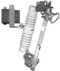
Overhead-Pole-Top Style 34.5-kV SMD-20 Power Fuse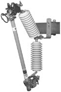
Station-Inverted Style 34.5-kV SMD-20 Power Fuse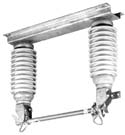
Station-Right-Angle Style 14.4-kV SMD-20 Power Fuse
Station-Vertical-Offset Style 14.4-kV SMD-20 Power Fuse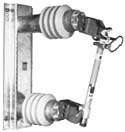
Station-Vertical Style 14.4-kV SMD-40 Power Fuse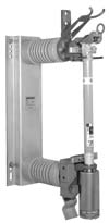
Opening and Closing Fuse Units
SMD-20 Power Fuses are equipped with attachment hooks for universal load switching using Loadbuster®, S&C’s portable loadbreak tool. SMD-40 Power Fuses are available with optional attachment hooks for full-load live switching with Loadbuster®.
SMD-20 and SMD-40 Power Fuses must not be opened under load without use of a Loadbuster.
Installing or Removing Fuse Units
SMU-20 Fuse Units can be installed in or removed from their mountings using a universal pole equipped with an S&C Talon™, Distribution Prong, or Station Prong. SMU-40 Fuse Units can be installed in or removed from their mountings using a Universal Pole equipped with an S&C Large Clamp.
Switching Overhead-Pole-Top Style SMD-20 Power Fuse using Loadbuster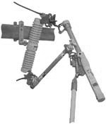
Installing the fuse unit in Overhead-Pole-Top Style SMD-20 Power Fuse using Talon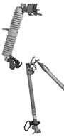

| Curve Type | kV Nom. Ratings | Fuse Type | TCC Number | Excel | |
|---|---|---|---|---|---|
| Minimum Melting | All | SMU-20 and SMU-40 | TCC Number 153-2 | EXCEL | |
| Total Clearing | 4.8 | SMU-40 | TCC Number 153-2-1-4 | EXCEL | |
| Total Clearing | 14.4 | SMU-20 | TCC Number 153-2-2 | EXCEL | |
| Total Clearing | 14.4 and 25 | SMU-40 | TCC Number 153-2-3-4 | EXCEL | |
| Total Clearing | 25 and 34.5 | SMU-20 | TCC Number 153-2-4 | EXCEL |
| Curve Type | kV Nom. Ratings | Fuse Type | TCC Number | Excel | |
|---|---|---|---|---|---|
| Minimum Melting | All | SMU-20 and SMU-40 | TCC Number 115-2 | EXCEL | |
| Total Clearing | 4.8 through 25 | SMU-40 | TCC Number 115-2-3-4 | EXCEL | |
| Total Clearing | 14.4 through 34.5 | SMU-20 | TCC Number 115-2-4 | EXCEL |
| Curve Type | kV Nom. Ratings | Fuse Type | TCC Number | Excel | |
|---|---|---|---|---|---|
| Minimum Melting | All | SMU-20 and SMU-40 | TCC Number 119-2 | EXCEL | |
| Total Clearing | 4.8 | SMU-40 | TCC Number 119-2-1-4 | EXCEL | |
| Total Clearing | 14.4 | SMU-20 | TCC Number 119-2-2 | EXCEL | |
| Total Clearing | 14.4 and 25 | SMU-40 | TCC Number 119-2-3-4 | EXCEL | |
| Total Clearing | 25 and 34.5 | SMU-20 | TCC Number 119-2-4 | EXCEL |
| Curve Type | kV Nom. Ratings | Fuse Type | TCC Number | Excel | |
|---|---|---|---|---|---|
| Minimum Melting | All | SMU-20 | TCC Number 176-2 | EXCEL | |
| Total Clearing | 14.4 | SMU-20 | TCC Number 176-2-2 | EXCEL | |
| Total Clearing | 25 and 34.5 | SMU-20 | TCC Number 176-2-4 | EXCEL |
| Curve Type | kV Nom. Ratings | Fuse Type | TCC Number | Excel | |
|---|---|---|---|---|---|
| Minimum Melting | All | SMU-20 | TCC Number 165-2 | EXCEL | |
| Total Clearing | 14.4 | SMU-20 | TCC Number 165-2-2 | EXCEL | |
| Total Clearing | 25 and 34.5 | SMU-20 | TCC Number 165-2-4 | EXCEL |
| Curve Type | kV Nom. Ratings | Fuse Type | TCC Number | Excel | |
|---|---|---|---|---|---|
| Minimum Melting | All | SMU-20 | TCC Number 175-2 | EXCEL | |
| Total Clearing | 14.4 | SMU-20 | TCC Number 175-2-2 | EXCEL | |
| Total Clearing | 25 and 34.5 | SMU-20 | TCC Number 175-2-4 | EXCEL |


