


Series 2000 Circuit-Switcher
Protect. Control. Isolate.
An all-in-one solution in a footprint-saving package, the low maintenance interrupters for straightforward installations are customized to your needs for 69-kV through 230-kV transmission applications.
Simplified design and complete factory assembly and testing mean the Series 2000 Circuit-Switcher can be relied upon to function properly day in and day out. And S&C’s comprehensive, easy-to-follow inspection recommendations, keyed to typical transformer inspection schedules, ensure the Circuit-Switcher continues to perform properly. The Series 2000 Circuit-Switcher’s reliability is backed by S&C’s 5-year warranty!
Series 2000 Circuit-Switchers provide these important features and benefits:
- A wide variety of mounting configurations. There’s a model to suit every substation layout and profile.
- Pre-engineered modular construction plus complete factory-assembly and testing. Dramatically reduces installation time. No costly, time-consuming field adjustments are needed.
- Superior reliability and economy. Series 2000 Circuit-Switcher’s simple, straightforward design means fewer parts — and lower initial and operating costs.
- Hermetically sealed, low maintenance SF6-gas-filled interrupters. Single-gap puffer-type interrupters maintain dielectric ratings when open.
- Optional remote-gas-density monitor. Includes dual-level low-gas-density alarms and system status contact.
(On mobile, swipe left for remaining ratings information.)
Voltage and Continuous, Short-Time, and Fault-Closing Current Ratings
| kV | Amperes, RMS | |||||
|---|---|---|---|---|---|---|
| Nom. | Max | BIL | Cont. | Short-Time | Fault-Closing, Duty-Cycle, One-Time | |
| Mom. | 1-Second | |||||
| 69 | 72.5 | 350 | 1200/2000 | 64 000 | 40 000 | 40 000 |
| 115 | 121 | 550 | 1200/2000 | 64 000 | 40 000 | 40 000 |
| 138 | 145 | 650 | 1200/2000 | 64 000 | 40 000 | 40 000 |
| 161 | 169 | 750 | 1200 | 64 000 | 40 000 | 40 000 |
| 230 | 242 | 900 | 1200 | 64 000 | 40 000 | 40 000 |
Interrupting Current Ratings for Transformer Switching and Protection
| Class | Qualifications | Maximum Amperes, Interrupting RMS Symmetrical | |
|---|---|---|---|
| Parallel Switching | — | 1200/2000 | |
| Load Dropping | — | 1200/2000 | |
| Fault Interrupting | Primary Faults | 69 kV through 138 kV | 25 000/40 000 |
| 161 kV and 230 kV | 20 000 | ||
| Secondary Faults | 4000 | ||
| Internal faults — see both primary and secondary faults, above | |||
Interrupting Current Ratings for Line Switching and Protection
| Class | Qualifications | Maximum Amperes, Interrupting RMS Symmetrical | |||||
|---|---|---|---|---|---|---|---|
| Load Splitting (Parallel or Loop Switching) |
— | 1200/2000 | |||||
| Load Dropping | — | 1200/2000 | |||||
| Line Dropping | 69 kV through 138 kV | 400 | |||||
| 161 kV | 320 | ||||||
Interrupting Current Ratings for Cable Switching and Protection
| Class | Qualifications | Maximum Amperes, Interrupting RMS Symmetrical | |||||
|---|---|---|---|---|---|---|---|
| Load Splitting (Parallel or Loop Switching) |
— | 1200/2000 | |||||
| Load Dropping | — | 1200/2000 | |||||
| Cable Dropping (Charging Current) |
69 kV through 138 kV | 400 | |||||
| 161 kV | 320 | ||||||
| Fault Interrupting | 69 kV through 138 kV | 25 000 | |||||
| 161 kV | 20 000 | ||||||
Interrupting Current Ratings for Single Shunt Capacitor Bank Switching and Protection
| Class | Qualifications | Maximum Amperes, Interrupting RMS Symmetrical | |||||
|---|---|---|---|---|---|---|---|
| Bank Current Switching | Grounded capacitor banks applied on solidly grounded systems only, through 138 kV | 400 | |||||
| Ungrounded capacitor banks through 115 kV | 400 | ||||||
| Fault Interrupting | — | 25 000 | |||||
Interrupting Current Ratings for Shunt Reactor Switching and Protection
| Class | Qualifications | Maximum Amperes, Interrupting RMS Symmetrical | |||||
|---|---|---|---|---|---|---|---|
| Reactor Current Switching | Grounded reactors applied on solidly grounded systems only, through 138 kV | 600 | |||||
| Ungrounded reactors, 69 kV only | 600 | ||||||
| Fault Interrupting | — | 25 000 | |||||
For Series Reactor Switching, contact your nearest S&C Sales Office.
For more detailed ratings and application information, see S&C Publication 716-31.
Series 2000 Model 2010 — Horizontal Interrupters and Vertical-Break Disconnect
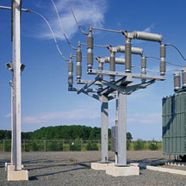
The Model 2010 is ideal for low-profile substations where an integral disconnect is required. The disconnect is operated in sequence with the interrupters.
Series 2000 Model 2020 — Vertical Interrupters and Side-Break Disconnect
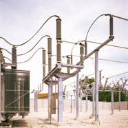
For substations where space is minimal and an integral disconnect is required, Model 2020 is an excellent solution. With its vertical-interrupter design, this model provides a low-cost means to include an integral disconnect because it uses shorter pole-unit bases and three fewer station-post insulators.
Series 2000 Model 2030 — Vertical Interrupters, Without Disconnect
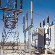
The Model 2030’s vertical-interrupter “candlestick-style” design ensures it will fit in the tightest of spaces. In this application, a Model 2030 was “shoehorned” into an existing substation where the distance between the transformer radiator and the footings for the non-loadbreak disconnect structure measured only seven feet.
Series 2000 Model 2040 — Horizontal Interrupters, Without Disconnect
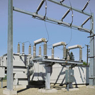
Model 2040 is the solution for low-profile substations where a separate disconnect is used.
Series 2000 Circuit-Switcher interrupters are driven by a single, stored-energy mechanism located at ground level. The operator directly drives the interrupters open and closed through a simple, high-speed power train. The power train leads from the top of the operator, through a horizontal interphase linkage enclosed in the steel-sheathed box-type base, to reciprocating-action insulated operating rods that pass through the hollow insulating support columns. The mechanism features instantaneous trip-free capability: if the Circuit-Switcher is inadvertently closed into a fault sensed by user-furnished relays, the mechanism will trip immediately.
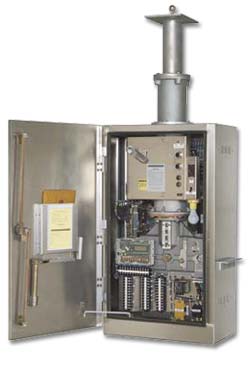
Other features of the operator include:
- Weatherproof, dustproof enclosure with front and side access doors.
- Trip and close push buttons.
- Non-reset electrical operation counter.
- Charged and discharged indicators.
- Manual-trip lever.
- Optional position-indicating lamps provide local indication of trip-coil continuity as well as open/closed status of interrupters.


